MPU6050 Sensor:
|
SUKKUR IBA UNIVERSITY Merit-Quality-Excellence DEPARTMENT OF ELECTRICAL ENGINEERING |
|
MPU6050 Sensor: |
|
|
|
Ref |
| Click Here to download datasheet. |
|
Click Here
to purchase online.
|
|
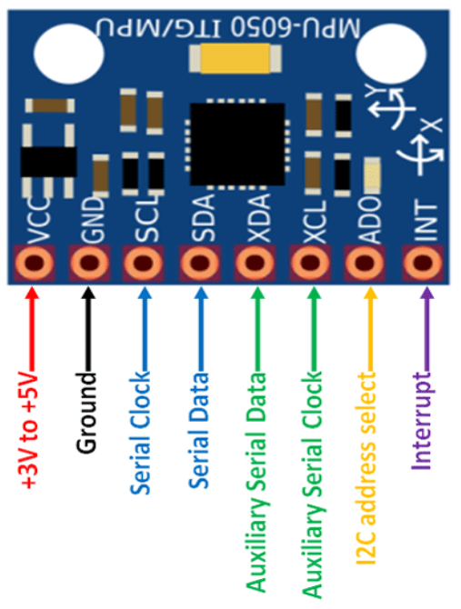
MPU6050 Pin Configuration: |
Pin Number |
Pin Name |
Description |
1 |
Vcc |
For providing power to the module, can be +3V to +5V. Typically +5V is used. |
2 |
Ground |
Used to connect the system to the ground. |
3 |
SerialClock(SCL) |
Used for providing clock pulse for I2C Communication. |
4 |
Serial Data(SDA) |
Used for transferring Data through I2C communication. |
5 |
Auxiliary Serial Data(XDA) |
Used to interface other I2C modules with MPU6050. (Optional) |
6 |
Auxiliary Serial Clock(XCL) |
Used to interface other I2C modules with MPU6050. (Optional) |
7 |
AD0 |
This pin is used when more than one MPU6050 is used on a single MCU. |
8 |
Interrupt (INT) |
Interrupt pin to indicate that data is available for MCU to read. |
|
Discription: |
|
The MPU6050 is a Micro Electro-Mechanical Systems (MEMS). Inside the MPU6050 there are 3-axis Accelerometer
and 3-axis Gyroscope. The parameters related to the motion of a system like acceleration, velocity, orientation,
displacement are measured using the data collected from them. There are also two auxiliary pins. These auxiliary
pins are used to interface external I2C modules. This module can very easily be used with any Arduino plateform by
installing some of the libraries.
|
|
Applications: |
Gyro is used in wide range of fields where position or orientaion of any object needs to be monitored. Some of the common uses are: • Used for IMU measurement • Drones / Quad copters • Self balancing robots • Robotic arm controls • Humanoid robots • Tilt sensor • Orientation / Rotation Detector |
|
Flysky-A8S Receiver: |
|
| Click Here to download datasheet. |
|
Click Here
to purchase online.
|
|
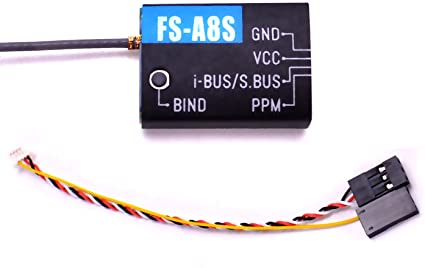
Flysky-A8S Pin Configuration: |
Pin Name |
Description |
Vcc |
For providing power to the module. |
Ground |
Used to connect the system to the ground. |
Receiver |
Used for receiving the data from the transmitter |
PPM Signal Port |
Output standard PPM signal. |
i-BUS/S.BUS signal port |
Outputs i-BUS/S.BUS signals, up to 18 channels |
|
Discription: |
|
The FS-A8S is a compact 1-way receiver designed for multi-rotor aircraft. It uses the AFHDS 2A (Automatic
Frequency Hopping Digital System) protocol, supports standard PPM output and has i-BUS support for up to
18 channels. As for drone our major concern mostly remains is its components weight. This FS-a8s fits the
specified requirements being only 20x14x5.3mm in size and 1.2gm in weight.
|
|
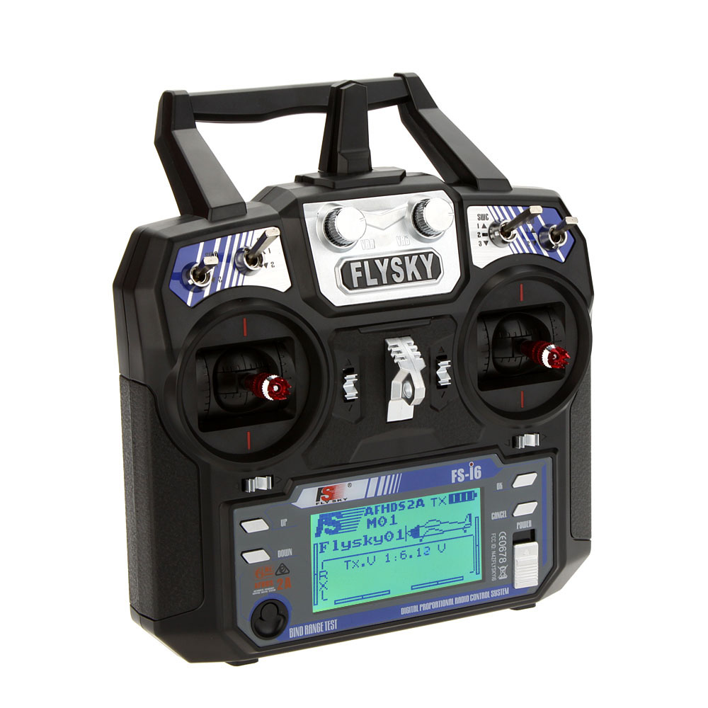
Flysky Transmitter: |
|
| Click Here for manual. |
|
Click Here
to purchase online.
|
|
Features: |
|
• Offering good protection against interference while maintaining lower power consumption and
high reliable receiver sensitivity. • Bidirectional Communication Capable of sending and receiving data, each transmitter is capable of receiving data from temperature, altitude and many other types of sensors, servo calibration and i-BUS Support(But in our case, we are only using uni-directional transmission: only to send data from transmitter to receiver). • Each transmitter and receiver has it's own unique ID. Once the transmitter and receiver have been paired, they will only communicate with each other, preventing other systems accidentally connecting to or interfering with the systems operation. |
|
Binding Receiver With Transmitter: |
|
We need to bind the transmitter with receiver when we are powering them for first time. Once they are in bind mode,
we do not need to bind them again until a new code is loaded into the microcontroller. The process of binding is
described below: • Power On the transmitter while holding the bind button. • If the receiver’s LED is flashing this means it is ready for binding. • If binding is successful, you can see an RX symbol appears at the top-right side of your transmitter display. • After successful binding, LED will stop flashing and remains solid. |
|
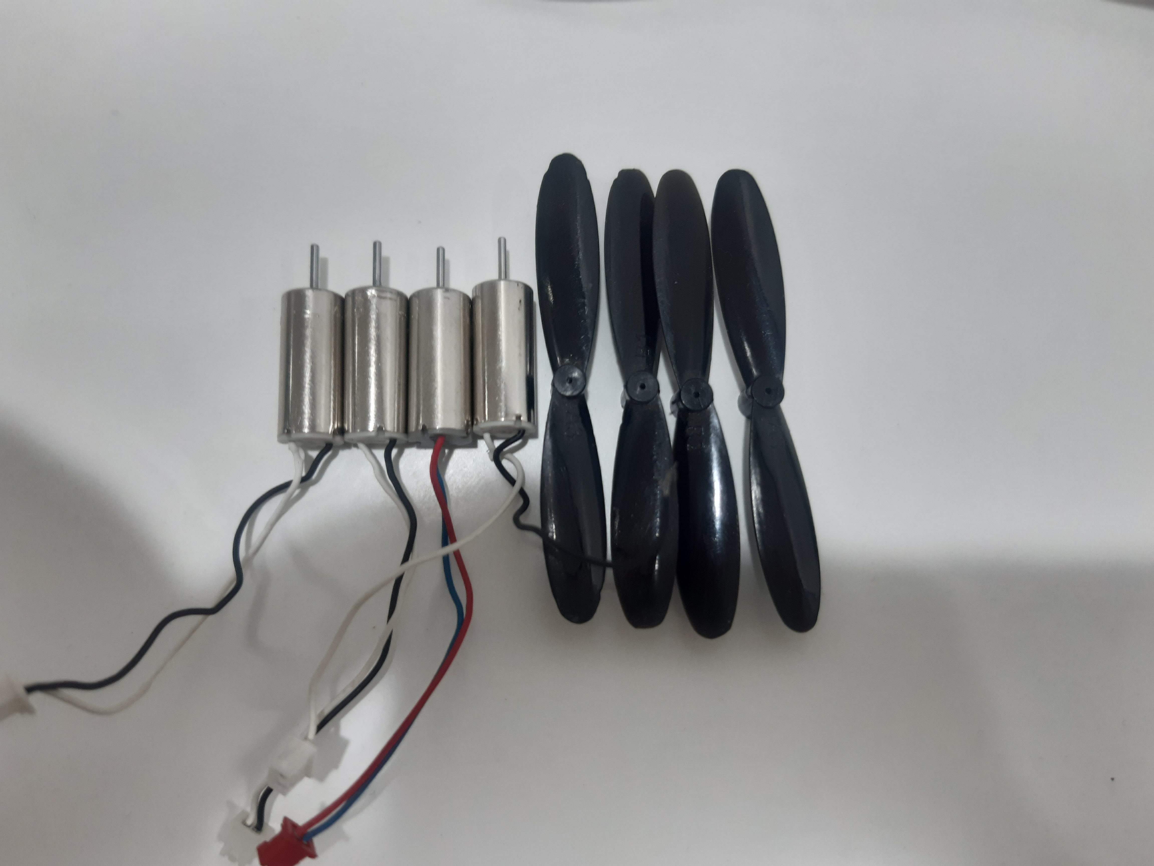
Coreless DC Motor And Propellers: |
|
| Click Here to buy online. |
|
Specifications Of Coreless Motors: |
|
• Material: Metal • Operating Voltage: 3.7 VDC • Rated Speed: 4200 RPM • Shaft Dimension: 3 x 0.5mm (L x D) • Body Dimension: 6 x 16mm (D x L) • Total Dimension: 19mm • Cable Length: 13mm |
|
About DC Motors: |
| As mentioned before, the key factor to make a drone successful is to make it light weight and choose the components that can provide more thrust. These motors that we have chosen for our project, meet these requirements. They are efficient in terms of power dissipation and have high RPM. These motors start rotating at 2.5V, but give full RPM at the voltage around 3.7V to 4.2V. |
|
About Propellers: |
| Propellers are essential components of a drone because they provide lifting force against the rotation of motors. One needs to do a deep research before choosing motors and propellers. Even if one buys motors having high RPM but fail to choose compatible propellers, it will be a failure. The propellers that we have chosen were best suited for 6*16mm motors. Buy right propeller and motors from the above mentioned link. |
|
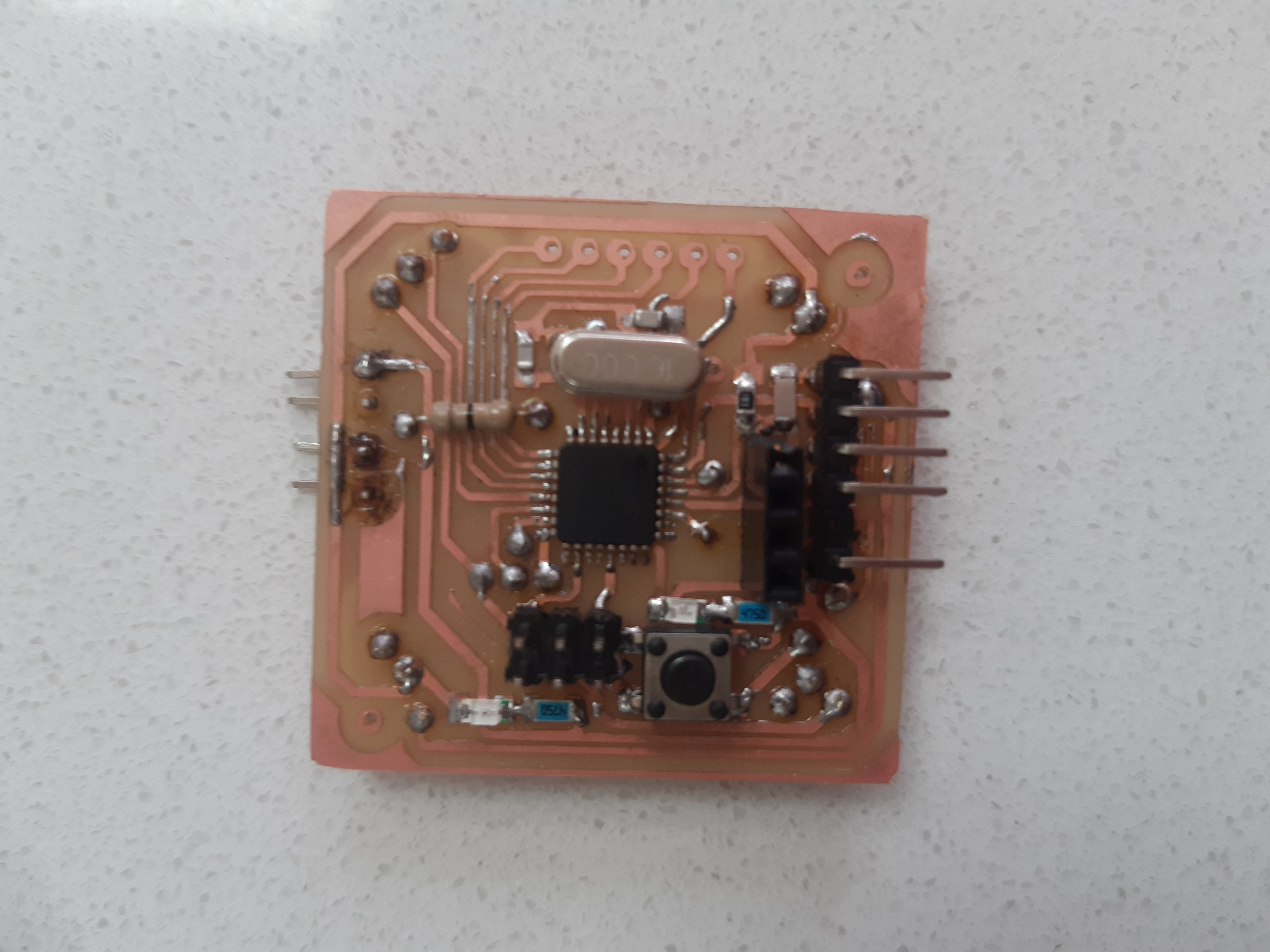
Flight Controller: |
|
As mentioned earlier, in the beginning we decided to work with NodeMCU, so we didn’t need to make any flight controller. But soon after not succeeding with NodeMCU we decided to make our own flight controller. The components required for making a fight controller are mentioned below. |
|
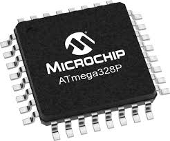
ATmega328P: |
|
| Pic Ref |
| Click Here for manual. |
| Click Here to buy online. |
Parameter |
Value |
CPU type |
8-bit AVR |
Performance |
20 MIPS at 20 MHz |
Flash memory |
32 KB |
SRAM |
2 KB |
EEPROM |
1 KB |
Pin count |
28 or 32 pin |
Maximum operating frequency |
20 MHz |
Number of touch channels |
16 |
Hardware QTouch Acquisition |
No |
Maximum I/O pins |
23 |
External interrupts |
2 |
|
Its Applications: |
There are hundreds of applications for ATMEGA328P: • Used in ARDUINO UNO, ARDUINO NANO and ARDUINO MICRO boards. • Industrial control systems. • SMPS and Power Regulation systems. • Digital data processing. • Analog signal measuring and manipulations. • Embedded systems like coffee machine, vending machine. • Motor control systems. • Display units. • Peripheral Interface system. |
|
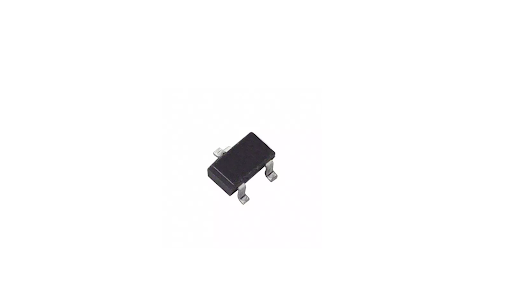
MOSFET(Si2302): |
|
| Click Here for manual. |
| Click Here to purchase online. |
For a flight controller we need 4 MOSFETs. As we are using 3.7 V battery, so we need MOSFETs that can operate on this voltage. We have used SI2302 because of its low power loses and Vgs. These MOSFETs start conduction at the voltages greater than 2.5 (Vgs voltage). This means that when we apply the control signal from GPIO pin having the voltage less than 2.5, the MOSFETs will act as an open circuit. But for voltages greater than 2.5 or 3 they will start conduction, and thus motors will start to rotate. As each motor is connected to separate MOSFETs, so we can control individual motor by changing the strength of control signal or voltage at the gate terminal of each MOSFETs. |
|
Some Other Basic Components: |
|
We also require some of the basic components for this project, including: SMD Components • 5V voltage regulator • One push Button • Resistor: One 10K and two 470 ohm • Crystal: One Crystal • lED’s : Two (3.7V) • Capacitor: Three 10uF, one 0.1uf and two 22pF • Male Headers: 14 L-Shape and 6 Stright. • Female Headers: 6 |
|
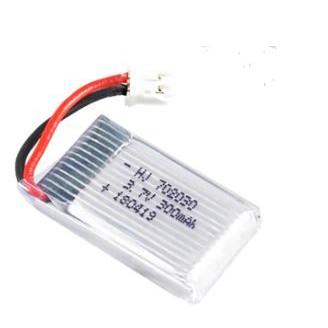
Battery: |
|
| Click Here to purchase online. |
For this project we have used 3.7 V LiPo battery because these batteries are light weight and have higher charge density than other batteries available in the market. We have actually designed our circuit that works both on a single battery (3.7 V) and also on two batteries in series(7.4 V). Depending upon our design requirements, we can use any of the options. More details about our designed circuit are available Here! |
|
Total Cost Of The Components: |
Components |
Price (Rs) |
| MPU6050 | 420 |
| Motors & properllers | 1550 |
| FS-a8s Receiver | 1620 |
| Fly-Sky transmitter | 5931 |
| Microcontroller ATmega328p | 240 |
| MOSFETs | 35 |
| Resistors | 150 |
| Headers, push button & LED's | 130 |
| Total cost | 10076 |
| Prev | Next |